
Analog Connections and the Touch Panel: AUDIO4c
Analog Connections and the Touch Panel: AUDIO4c
More Connections than you can Shake a Stick at!
So you’ve bought (or are thinking of buying) an iConnectivity AUDIO4c? Great choice! One of the reasons the AUDIO4c is so flippin’ versatile is down to its huge levels of connectivity. In this blog we’re going to focus on the analog connectivity on offer, and how you can make the most of it.
Understanding the Input Channels
AUDIO4c offers you four analogue input channels which will accept a variety of connectors, levels and impedances. “Wait, what the heck does all that mean?” you might be asking. “I just want to plug in my mic, guitar and synth!”
Well, don’t worry, this blog is here to act as a guide to help you understand what to plug in and where. There’s going to be a little bit of engineering theory here, but nothing you’ll need a degree from MIT to understand!

AUDIO4c Front Panel
Combo Connectors - how do they work?
Take a look at the front of your AUDIO4c and you’ll see four big connectors on the front of the interface. These are clever combo connectors that will accept both balanced XLR connectors as well as balanced and unbalanced ¼” jack connectors.
If you’re unsure what the difference between those connectors is, then check out our blog on analogue connectors. Typically a microphone will be on a balanced XLR connector, pro audio gear may be on a balanced ¼” jack, and guitars use unbalanced ¼” jacks.
To put things simply, you can plug in a balanced XLR connector from your microphone, a balanced line-level ¼” jack from a piece of audio gear, or an unbalanced ¼” jack from your guitar.
Input Settings and Levels
OK, so you’ve got all your gear connected to your AUDIO4c. Let’s imagine for this example you have a condenser microphone connected to input 1, and your electric guitar connected to input 2.
Let’s get your microphone set up first; as it’s a condenser mic you’ll need to send it phantom power. Hit the 48V/Inst section of the touch panel with your finger and make sure it lights up green. Then, in this instance, tap channel 1 until that lights up green. You’ve now successfully sent phantom power to your microphone.
Now, let’s turn up the input gain on your microphone. Make sure you have input 1 selected and turn the knob on the front of the interface. As a guide, set your input level so your loudest sound peaks the meters into amber.
Next, let’s set your guitar input. Most electric guitars and basses use high impedance pickups. We, therefore, need to use the AUDIO4c’s Instrument setting on input two.
Make sure that you have input 2 only selected. Now, tap the 48V/Inst section of the touch panel until the light turns red. Set your input gain as above and you’re ready to rock!
Understanding Output Channels
Spin your AUDIO4c around and on the back panel, and you’ll see five, ¼” jack sockets. Outputs 1-4 are balanced, mono, line-level channels. The output labelled “phones”, perhaps unsurprisingly, is designed for headphones!
Thanks to some clever design though, you can use these output channels for more than just connecting your studio monitors and headphones…
Phantom Safe for Live Shows
Because the AUDIO4c offers balanced line-level outputs, you can connect the output of your AUDIO4c directly to a stage box. All you need is a TRS-to XLR loom and you can save yourself a bunch of cash on DI boxes!
If you want to understand more about connecting your audio interface, live, then read our blog on connecting to a venue’s PA system.
There’s one potential problem with this, however; it’s possible for a venue’s engineer to accidentally send phantom power to the outputs of your audio interface. Ordinarily, this would cause severe damage. However, we’ve designed the AUDIO4c to be immune from stray phantom power for your peace of mind.
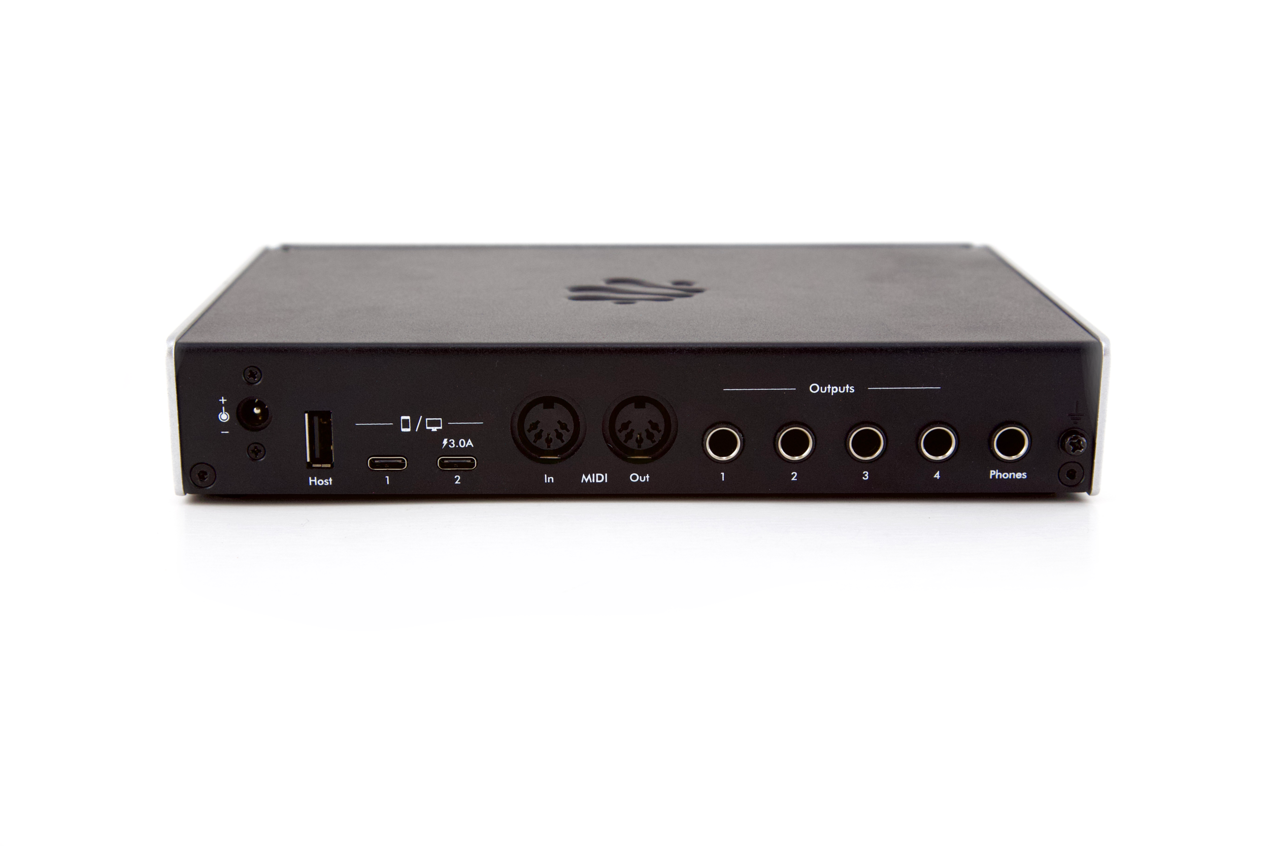
AUDIO4c Back Panel
Making the most of your Headphone Output
We designed the headphone output on the AUDIO4c so that it could drive just about any pair of headphones. It’s also powerful enough for you to use it as a monitor in loud environments (just be kind to your ears OK?).
However, if you’re in a pinch, and need another pair of mono outputs, then you can use the headphone output for another pair of discrete outputs. To do this, you’ll need a ¼” TRS to twin mono jack lead. This kind of lead is sometimes sold as an “insert cable” by the way.
If you do decide to use the headphone output in this way, be aware that you’ll need to trim the output level down a lot compared to your line outputs. You must also protect it from Phantom power if plugging it into a mixing desk; we’d advise running these outputs into a pair of DI boxes to be safe!
Setting Output Levels
Just as we set the input levels using the touch panel and controller knob, we can set the output levels. Select which output you want to adjust, by touching the relevant section on the panel, and then use the rotary encoder to increase, or decrease the level.
Level Displays
Set some music playing and hit the output button so it shows green. The bar graph display on the right will show you the real-time output levels for that channel. Great for diagnosing signal flow (plus, who doesn’t love some dancing lights eh?).
Tap the button again and it’ll turn red. The level display now shows the output gain of that channel. Think of it as the line on the volume knob on a home stereo if you like!
Bonus Features!
The rotary controller knob does more than just set input and output levels. It has multiple other functions activated by pressing the knob in.
Save Settings - press and hold until the display flashes
Power off - press and hold until interface powers off
Power on - tap knob once from power-off state
Level Up!
After all of that, you should now count yourself as an expert in controlling and understanding the analogue inputs and outputs of your AUDIO4c. Here’s our friend Will with a friendly video guiding you through everything we’ve just covered!